Parking Guidance Display Hardware: LED Signs, Variable Message Signs, and Counting Systems
Parking guidance systems reduce circulating traffic within facilities, improve driver experience, and provide operators with real-time occupancy data. The display hardware that communicates available spaces to drivers — from entrance count signs to zone indicators to individual space indicators — represents a significant portion of the total system cost and has a direct impact on whether drivers actually use the guidance.
This guide covers the display hardware categories used in parking guidance systems, their technical specifications, and the integration requirements for a functional system.
Entrance Count Displays
Entrance count signs show the total number of available spaces in a facility or zone, typically mounted at the entry decision point before drivers commit to entering. These are the highest-visibility displays in a guidance system — they influence whether drivers enter the facility at all.
LED Matrix vs. Segmented Displays
Segmented LED displays use fixed 7-segment LED arrangements, similar to a digital clock display. They are cost-effective for showing numeric counts and simple text. The limitation is fixed character formats — a 7-segment display cannot show variable-width messages or custom icons.
LED matrix displays use a grid of individual LEDs that can form any character or graphic. They are more expensive but provide full alphanumeric capability, allowing display of counts alongside status messages (“FULL,” “RESERVED,” “LEVEL 2: 47 OPEN”).
Brightness and Visibility
Outdoor entrance signs must be readable across a 50–100 foot viewing distance in direct sunlight. Minimum luminance of 8,000 cd/m² (candelas per square meter) is typically required for direct sunlight readability; premium outdoor signs specify 12,000–15,000 cd/m². Automatic brightness control adjusts output based on ambient light levels, preserving night vision for approaching drivers while maintaining daytime readability.
Red LEDs historically dominated count signs because early high-brightness LEDs were only available in red. Modern full-color LED signs use RGB LEDs that can display green (open), yellow (limited), and red (full) — though most guidance applications still use a standardized color scheme.
Standard color coding (ITE recommended practice):
- Green: spaces available
- Yellow/Amber: limited availability (typically 10–20% occupancy threshold)
- Red: full or near-full
Zone and Level Indicators
Within a facility, zone and level signs direct drivers to the floor or area where spaces are available. These signs are typically smaller than entrance signs and mounted at decision points — ramp entrances, elevator lobbies, major intersections within the facility.
Zone signs face the same brightness requirements for artificially lit garage environments. Indoor parking structures are often poorly lit, making high-brightness LEDs unnecessary; however, near-entrance zones with natural light ingress may still require higher-brightness specifications.
Mounting and Cabling Requirements
Parking guidance signs require both power and data connections. Power options include:
- Standard AC power — requires conduit runs to each sign location; most common in new construction
- PoE (Power over Ethernet) — emerging in mid-sized LED signs that can operate within 25–30W PoE+ budgets; eliminates separate power conduit
- DC bus systems — some manufacturers use a shared DC bus topology, reducing cable runs in large facilities
Data connectivity options include Ethernet, RS-485 (older installations), and wireless (WiFi or Zigbee mesh). Hardwired Ethernet is preferred for reliability in production installations.
Individual Space Indicators
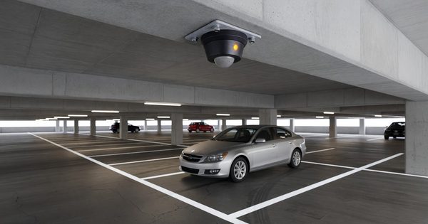
Individual space indicators — small LED lights mounted above or adjacent to each parking space — provide the most granular guidance, directing drivers directly to specific open spaces within a row or zone. Combined with overhead sensors, they visually indicate which spaces are open (typically green) and which are occupied (red).
Specifications for Individual Space Indicators
Individual space indicators operate in the typical LED viewing angle range of 120–160 degrees for good horizontal visibility as drivers proceed down a row. Mounting height of 7–9 feet provides visibility while minimizing obstruction for tall vehicles.
Most individual space indicators are addressed devices — each unit has a unique address on the communication bus, allowing the system to update each indicator individually rather than broadcasting to all devices simultaneously.
Communication protocols used in individual space indicator networks include:
- DALI (Digital Addressable Lighting Interface) — originally for lighting control, adapted for indicator applications
- CANbus — common in automotive-derived systems
- RS-485 Modbus — robust for industrial environments
- Proprietary protocols — most manufacturer-specific implementations
Variable Message Signs (VMS)
Full-matrix variable message signs at facility entrances and directional decision points can display dynamic messages beyond simple counts: event parking instructions, rate information, construction notices, emergency messages.
VMS hardware relevant to parking applications typically uses amber or full-color LED matrices with character heights of 8–18 inches. Transportation VMS applications are governed by NTCIP (National Transportation Communications for ITS Protocol) standards, which some parking guidance systems have adopted to leverage the ecosystem of compliant management tools.
Integration Architecture
A parking guidance system is only as accurate as its occupancy data. The display hardware requires integration with occupancy detection (sensors, LPR, counters) through a guidance management platform that:
- Aggregates real-time occupancy from all detection points
- Calculates available space counts by zone and level
- Pushes updated counts to display hardware
- Provides a management interface for thresholds, messaging, and system status
Update latency — the time between a space changing state and the display reflecting that change — affects driver trust in the system. Latency above 30–60 seconds causes visible inconsistencies that erode confidence. System architectures should specify maximum end-to-end update latency as a performance requirement.
FAQ
What is the typical lifespan of LED parking guidance signs? Quality LED signs have a rated L70 lifespan (time to 70% of original brightness) of 50,000–100,000 hours, equivalent to 11–22 years of continuous operation. In practice, power supply components and communication hardware often require attention before LED degradation becomes visible. A 10–15 year service life before major refurbishment is a reasonable planning assumption.
Can parking guidance displays be integrated with external platforms via API? Most modern parking guidance management systems expose RESTful APIs that allow real-time occupancy data to be published to external platforms — mobile apps, parking aggregators, city parking portals, and navigation systems. APDS (Alliance for Parking Data Standards) data formats facilitate standardized data exchange between parking systems and third-party platforms.
What maintenance does parking guidance hardware require? LED signs require periodic cleaning of diffuser panels (dust accumulation reduces brightness), inspection of mounting hardware, and firmware updates via the management platform. Individual space indicator systems require more frequent attention due to higher component counts; annual audits to identify failed indicators are standard practice. Battery-powered wireless sensors in the occupancy detection layer require battery replacement on 3–7 year cycles.
How should parking guidance systems handle partial sensor failures? Guidance management platforms should detect sensor anomalies (sensors reporting impossible patterns, sensors offline) and exclude failed sensor data from count calculations. Graceful degradation — falling back to counter-based estimates when individual sensor data is unreliable — prevents guidance displays from showing wildly inaccurate counts due to a small number of failed sensors.